Why use parallel seismic survey methods?
The parallel seismic survey method is a nondestructive test (NDT) that assists with estimating the depth of a sheet pile, foundation, or pile below a foundation. Unless there is a need to confirm the construction of a new pile, characterizing dated structures is the primary application. For example, surveys may focus on determining the depths of piles at failing bridge foundations, for current applications that require new load requirements, or at a renovation project that will reuse old pilings for a new application.
Parallel Seismic Survey Method Tests and Instruments
What is a parallel seismic test?
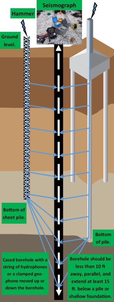
A parallel seismic test maps first arrival times of a seismic pulse as a function of depth from within an adjacent borehole. The body wave, often called a seismic wave, seismic pulse, or compressional wave travels down a foundation or a pile, after a pile or cap is struck with an impact source. As the wave propagates down the foundation and/or pile, the wave radiates into the soils and intercepts the adjacent borehole.
As a result, one can record the pulse with a receiver in the borehole. For this purpose, an operator will often lower a geophone or a hydrophone down a cased borehole at predetermined increments (typically less than two-foot increments). At each increment in depth, a seismic pulse is created by hammering on the top of a pile surface, pile cap, or sheet pile. The parallel seismic instrument (e.g. Geometrics Geode seismograph or ABEM Terraloc) is trigger to record at the hammer’s point of impact. An interpretation of the seismic records leads to an estimate of the depth to the pile tip.
Why does parallel seismic work?
Parallel seismic methods record the impact response of a hammer blow at depth. With good site conditions, the average velocity of the seismic wave traveling down the foundation and pile to the borehole is fairly constant, until it reaches the pile tip. The apparent velocity beyond the pile tip decreases because of slower velocity soils and an increase in the travel distance within soils. To explain, the travel time between the pile and borehole is somewhat constant for the length of the pile. Below the pile tip the distance the pulse travels within soils increases as the borehole increases in depth below the pile tip. In addition, the travel time also increases because the pulse propagates at a slower rate through the soils, which increases in distance below the pile tip. Consequently, there is a distinct change in character of the seismic pulse below the pile tip.
An interpretation of the seismic record provides a depth estimate for the foundation or pile tip. The greater the velocity contrast between the response from along the pile and the zone below the pile the easier the interpretation. In my opinion, parallel seismic tests are better suited for higher density pile materials (e.g., concrete and steel). Piles with greater density offer higher p-wave velocities that are hopefully much greater than the soils between the pile and the borehole. Lower density materials offer lower p-wave velocities. While body waves are generated when a lower density pile is struck, it is less clear how the waves propagate. To illustrate, if the density of the pile material was identical to the surrounding soils then the p-wave velocities should be nearly identical. Without a density contrast, the preferential travel path for the body wave is likely less predictable and potentially less focused.
Parallel Seismic Instruments
There are two major categories of instruments when it comes to parallel seismic surveys. The first group integrates geophysical equipment that is capable of acquiring data for many types of seismic services (e.g., seismic refraction, reflection, multichannel analysis of surface waves or MASW, crosshole seismic surveys, and shear wave seismic surveys). The second group (e.g. Olson Instruments or Piletest) has instruments specifically for parallel seismic survey methods.
As a geophysicist, I prefer to use commercial geophysical instruments designed to acquire multichannel records (e.g., ABEMS Terraloc or Geometrics Geode). These instruments offer filters to maximize signal to noise and can display multiple channels while in the field, which improves quality control. When the parallel seismic survey test has saturated conditions at depth, one can use a hydrophone or a string of hydrophones in a water-filled borehole. I use a three component or triaxle geophone, which does not require water. The instrument (e.g., Geostuff’s borehole geophone) clamps inside the casing with a motorized spring. While there is some discussion on the benefits of three components, case histories support the vertical component or a component that aligns with the vertical axis of the pile yields consistent results.
Parallel seismic limitations and concerns
With good conditions, it is common for the parallel seismic survey method to have less than 10% error, at times less than 5%. Other than ambient noise generated by local facilities, the borehole and surrounding borehole conditions are potential sources of error. First, the method assumes that a reasonably competent pile exists at depth. Otherwise, the pile would be of little use. Above all, engineers and other professionals using the results of a parallel seismic survey test should know that there are no guarantees. Like all geophysical methods, the indirect method of observing conditions at depth is not always as clear-cut as one expects. Unexpected complex conditions at depth can produce undesirable results.
Borehole conditions
Of course, the parallel seismic survey method requires a borehole. Unless the program conducts a deviation or directional survey, the borehole must be parallel and follow the shortest path from the surface to the bottom of the sheet pile, as close as possible to the pile, and extend more than fifteen feet below the pile. When the boring is not parallel, angled, or is greater than ten feet from the pile, the amount of error typically increases. Tilted piles may yield apparent depths to the pile tip. Unsaturated soils or poor drilling conditions that produced irregular borehole conditions, which creates borehole effects, may require grouting. To generate a seismic pulse the operators needs good access to strike the top of the pile surface, pile cap, or sheet pile, within the immediate vicinity of the borehole.
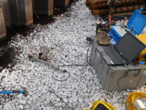
Parallel seismic survey test instruments.
Soil conditions
Interpreting parallel seismic results is more difficult or sometimes impossible when the soils are not homogeneous and isotropic. That is to say, large boulders, some types of fill, or interbedded clays, sands, and gravels can complicate the seismic record. In my opinion, the most basic function of the parallel seismic survey method is to assist with estimating the depth (apparent depth of slanted piles) of a pile tip. While others claim to characterize soil conditions and the condition of a pile, one should be careful. Issues with the quality of the seismic pulse, lateral variations in soils, and misplacement of the borehole can undermine the confidence of the interpretation. That is, it may be too difficult to differentiate between the condition of a pile and adverse subsurface effects (e.g. borehole effects or horizontal and vertical changes in soil conditions at depth).
Parallel seismic test report
Assuming one does not detail the theory or include seismic records on a per shot basis, the report is frequently short and to the point. While adverse conditions can clearly complicate an interpretation, the test results are usually straightforward and ready for an engineer to incorporate into a project. First, one will see that the response from each location down the borehole yields a seismic wave form. Personnel reporting the results interprets the first breaks. If all goes as planned, two zones of interest appear. The first zone represents the response from above the pile tip and the second zone below the pile tip.
Region above the pile tip
For above the pile tip, one should observe a clear linear set of first arrivals. A well-fitted straight line passing through the first breaks should yield a slope that reasonably approximates the average velocity of the foundation, pile, or sheet pile. Another characteristic of this region is the quality of the waveforms. Typically, the waveforms are better defined with higher frequencies and greater amplitudes. To repeat, this region is characteristic of the zone adjacent to the pile, not the tip. Thus, if one is searching for a minimum pile depth and it falls within this region, additional interpretations may not be necessary. One may be comfortable assuming the pile exceeds the minimum depth requirements.
Region below the pile tip
The zone below the pile tip may yield a more poorly defined set of first breaks that yields an average velocity less than the pile. This zone frequently shows a distinct loss of energy and has a lower frequency response. In addition, it may include a portion of the first breaks that represent a transition from the pile tip to the zone well below the pile tip. Unless one wishes to attempt to characterize the soils based on these results, the accuracy of determining the average velocity for this region is likely less important.
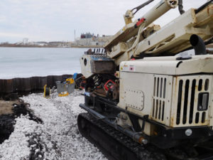
Drill rig used for parallel seismic survey tests.
On the other hand, one needs to take care to identify a good approximation for the region well below the pile tip. This analysis and the selection of a line defining the first breaks is part of the results used to interpret the depth of the pile tip. Further interpretation is likely unnecessary if the minimum pile depth falls well into this region. That is to say, an interpretation suggests the depth to the pile tip is less than the minimum requirements.
Depth of the pile tip
Finally, the actual depth of the pile tip is available from two interpretations. Undoubtedly, the most common interpretation is the intersection point of the lines defined by the first breaks obtained for the zones above and below the pile tip. The depth the two lines intersect on the seismic record is considered a reasonable approximation for the depth of the pile tip. With good site conditions, the error for the depth estimate is expected to be less than 10%, sometimes less than 5%.
A less common interpretation is the depth that one observes the emergence of a diffraction pattern. The diffraction pattern is created by the seismic waves responding to the pile tip, which is an abrupt discontinuity. A diffraction appears in the seismic record as a “V” shaped pattern. The bottom of the “V” or the vertex approximates the depth of the pile tip. The wave theory describing the cause of this event is outside this discussion. Nonetheless, it is an important anomalous feature worth noting.
Types of Piles for foundation systems
There are more flavors of piles and foundations than there are type of tomatoes. Wikipedia and other sites on the internet provide more detail than this brief overview. First, structures utilize a variety of materials for their pilings. For example, wood timbers, iron or steel, prestressed concrete, or a combination of steel and concrete are common. Depending on the application, one will find driven piles, drilled piles, specialty piles, and piled walls.

Parallel seismic test on foundations for reuse.
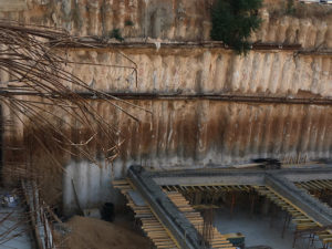
Parallel seismic tests for piled wall.
As the term implies, driven foundations use a pile driver to drive reinforced concrete, steel, or large wooden poles into the ground. If driven foundations are insufficient, then one may excavate or drill holes to construct a pile. Drilled piles include caissons, drilled shafts, drilled piers, Cast-in-drilled hole piles (CIDH piles), or Cast-in-Situ piles. When more ordinary pile construction is not advantageous, structures may depend on micropiles, tripod piles, sheet piles, soldier piles, screw piles, suction piles, and walls created by piles or piled walls.
References
E. Niederleithinger. Improvement and extension of the parallel seismic method for foundation depth measurement. Soils and Foundations, (52):1093{1101, 2012b.
Olson. Parallel seismic. Technical report, Olson Engineering: Experts in nondestructive evaluation.