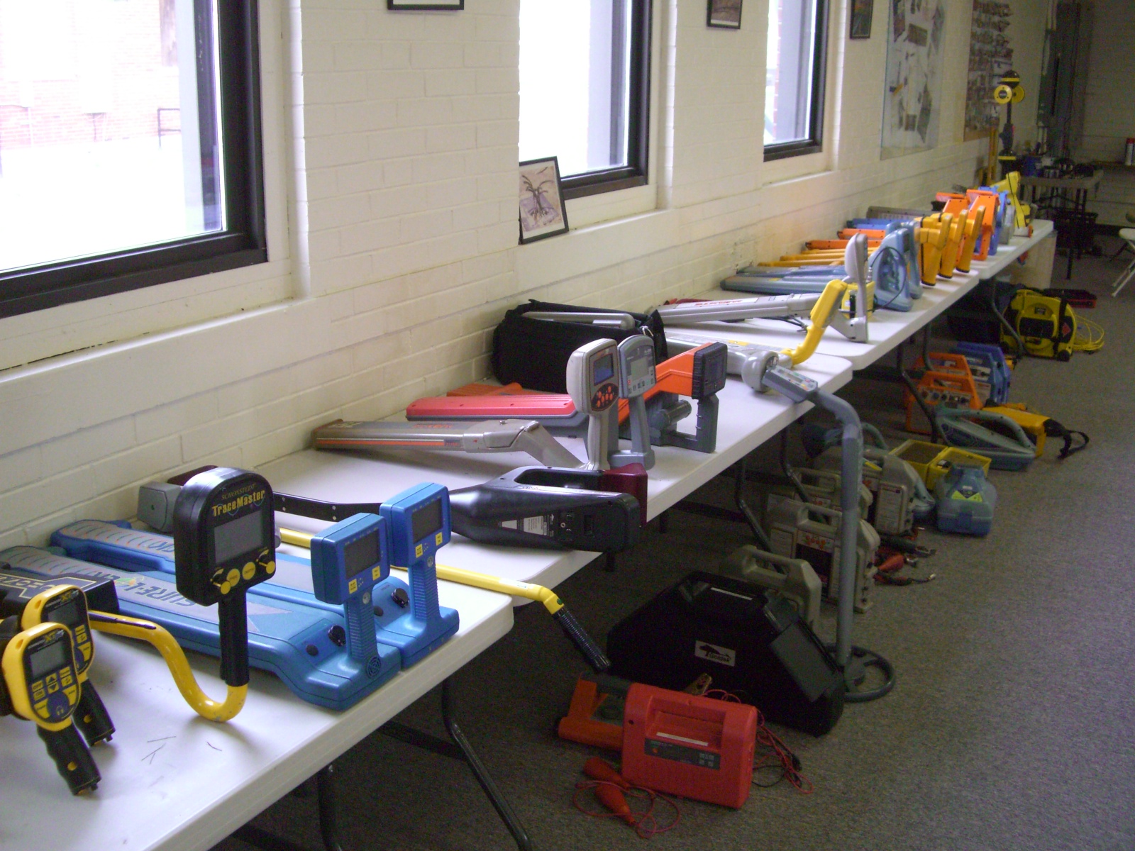
Use geophyics (GPR, MASW, EM, ERI, magnetometers, and line locators)
Geophysics can assist with characterizing voids and unstable soil conditions. Over time, voids can form under foundations, buildings, and parking lots. These spaces and adjacent unstable local conditions are often created by epikarst activity, collapsing sinkholes, erosion, and flowing water. These voids can cause dangerous structural instabilities in the surrounding areas and necessitate excavation or repair work that can disrupt daily lives. But there is a way to detect these features without having to dig up entire areas: geophysical methods. Geophysical methods are non-invasive techniques using math and physics relating to electromagnetic fields, electrical current flow, and acoustic energy passing through the subsurface for mapping underground conditions. In this post, we will discuss the various cases for geophysical methods for detecting possible subsurface voids under foundations, buildings, roads, etc., as well as how they compare against traditional exploration techniques like excavating or boreholes drilling.
Overview of geophysical mapping techniques for voids, sinkholes, and other
Geophysical mapping is a valuable approach to investigate the subsurface characteristics near and under buildings, pavement, and accessible areas. The technique offers a non-invasive way of rapidly surveying a site and obtaining significant data about subsurface conditions. It mainly relies on ground penetrating radar (GPR), electromagnetic induction, multichannel analysis of surface waves (MASW), electrical resistivity imaging (ERI), magnetometer surveys, and line locator instrumentation. Each system has its advantages and disadvantages, making it suitable for different applications. Seldom does one approach yield the detail and analysis provided by integrating methods. For example, GPR is good at imaging soils at shallow depths but highly influenced by groundwater; whereas MASW can generate images to detect voids at greater depths beneath the ground and is not influenced by groundwater or fluids. When integrated, these tools provide a more extensive overview of the site, one that would be difficult, if not impossible, through drilling or excavation processes.
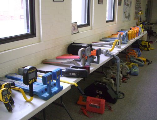
Types of methods used in geophysical mapping
Near surface geophysical surveys and mapping are techniques used to obtain data about the subsurface. They typically involve collecting information at the surface along profile lines or grid patterns. There are many methods of geophysical mapping that can be used, including Ground Penetrating Radar (GPR), Multichannel Analysis of Surface Waves (MASW), Electromagnetic terrain conductivity methods (EM), Electrical Resistivity Imaging (ERI), magnetometers, and line locators.
- GPR offers some of the greatest detail and ability to locate small features, with good site conditions. While many are familiar with GPR being used to locate utilities, it is very useful for imaging concrete and conditions immediately below a concrete slab.
- MASW is commonly a good choice in nearly any environment where the geophones can couple to the ground; however, resolution is strongly dependent on depth.
- Like MASW, ERI has roughly the same resolution as MASW. However, groundwater can impact the results if one is looking for areas of concern that are not related to groundwater issues.
- Electromagnetic terrain conductivity surveys (EM) are, in my opinion, very cost effective. For a fraction of the cost, one can map lateral variations across a survey area. While EM is very sensitive to lateral variations, it takes a fair amount of effort to determine how the variations occur as a function of depth.
- Magnetometer surveys are very cost effective but only reveal sources of buried iron, the type a magnet is attracted to. Cultural interference can be an issue, especially when searching for smaller targets.
- Line locators are very cost effective and really only good for locating metal pipes, cables, manhole covers, storm drains, and other very near surface metal features.
Ground Penetrating Radar (GPR)
Depending on conditions, target size, and depth, Sensors & Software’s Noggin 250MHz, 500MHz, 1000MHz, Conquest 1000MHz, and pulseEKKO Ultra Ground Penetrating Radar (GPR) systems are capable of imaging the near surface. The 1000MHz systems provide amazing detail between 1in and 24in. The lower frequency units (50MHz to 500MHz) are often able to penetrate depths between 1 and 50 feet. This tool is commonly used for a range of applications in geology, engineering, and construction. GPR is non-invasive and capable of generating detailed maps with little or no interference to nearby activities. Radar technology detects changes in electrical properties of materials beneath the surface, such as buried metal, changes in groundwater levels, soil composition and compaction, fill materials, hollows spaces, and non-metallic objects buried in the ground. GPR offers the highest level of detail when compared to EM terrain conductivity meters. For example, with GPR, you can map cracks in concrete that would otherwise go undetected. By using advanced imaging software, data collected by a GPR scan is then combined to create two-dimensional or three-dimensional images for further inspection. On the other hand, GPR is a time-consuming process and demands significant effort when it comes to surveying thousands of square feet. Under most circumstances, the results will furnish a client with information on location, size, and depth of potential targets of interest.
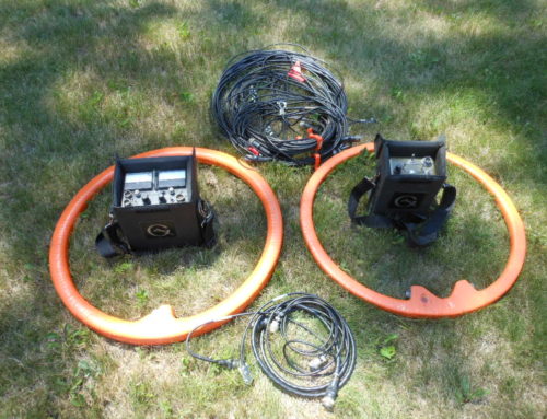
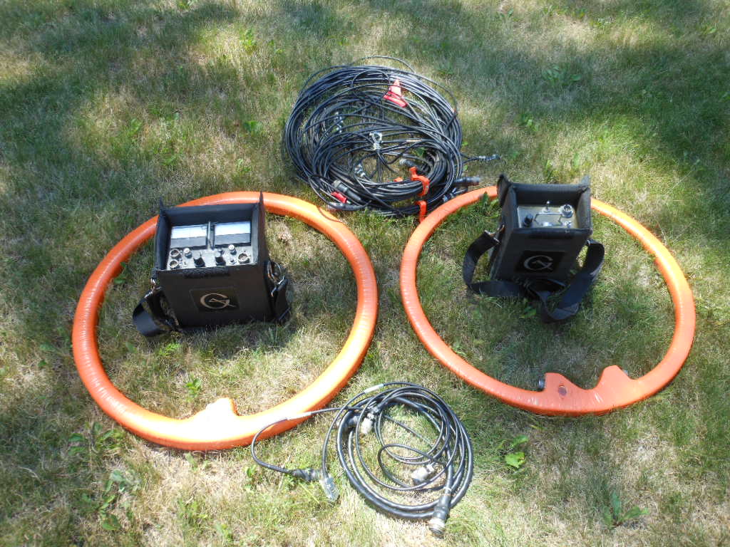
Multi-channel analysis of surface waves or MASW
During a MASW survey, variations in soil stiffness are often identified and mapped, as well as air or fluid filled voids hidden beneath the subsurface. MASW is efficient for covering large areas, proving far more rapid than drilling, probing, or excavating. With data collection requiring minimal disruptions and disturbances to local activities, this makes MASW a reasonable choice for mapping targets inside or outside a building. To begin the MASW process, a series of geophones are laid out. Then to create seismic waves for near surface targets, an operator usually uses a small to medium weight sledgehammer and plate. A seismograph transforms the resulting vibrations into digital signals for analysis.
Through MASW post-processing software and analysis, information on bedrock, soil composition and compaction, fill material, voids, and other insights can be revealed. Successful MASW surveys are contingent on a variety of factors, including target depth and size, number of geophones utilized in the survey, source-receiver geometry, and frequency content. Moreover, nearby structures or industrial facilities should not disrupt the performance of MASW to ensure reliable results. By combining MASW with other geophysical techniques like EM, GPR and ERI, one can generate a more comprehensive understanding of the subsurface environment.
Electromagnetic Methods Using Geonics Instruments
Geonics is the premier producer of electromagnetic terrain conductivity meters, trusted by a wide array of industries including engineering, archeology, military, and more. Their instruments are renowned for their reliability, repeatability, and accuracy. The instruments generate electrical currents through electromagnetic induction and measurements are gathered along survey lines. Once these readings have been processed, they can be depicted in maps that reveal anomalies related to metal or variations in groundwater, fill, soils, or rock.
There’s no denying that the EM31 is highly regarded for its extraordinary subsurface investigation capabilities. It stands out among other electromagnetic instruments like the EM38. An EM38 system offers higher resolution than either an EM31 or magnetometer ands its upper-frequency range provides greater detail. The EM31 is the standard tool for surveying conditions that range between 5 and 20 feet deep. For shallower depths of penetration, approximately 3 to 12ft, the EM31 short is a good option. In very shallow applications an EM38 with its short coil spacing is preferred for depths between about 1 to 5ft. In addition to mapping variations in local geology, these tools are especially effective when searching for shallow facilities such as pipes, cables, and tanks, which can induce groundwater flow that results in washouts or cavities. These targets can eventually produce voids or openings at the surface.
Electrical Resistivity Imaging (ERI)
AGI’s SuperSting R8 electrical resistivity imaging system is well known and used by geophysicists, geologists, engineers, hydrogeologists, and other specialists to explore the subsurface. ERI is a geophysical method that utilizes electrical currents to measure dissimilarities in electrical resistance below the ground’s surface. By placing ERI lines over areas of concern, cross-sections are generated for mapping both natural and manmade features at depth. Unlike EM and magnetometer methods, ERI offers greater resolution at depth and detail in both two-dimensional (2D) images as well as three-dimensional (3D) presentations, when multiple lines are acquired.
When performing an electrical resistivity imaging survey, direct current (DC) electrodes are used to measure the differences in resistance below the surface. One downside is that it takes extra effort to collect data over paved areas or within a building’s interior, since an operator needs to drill holes for the electrodes to reach the soil. The arrangement of the electrodes determines the depth and resolution of an investigation. The end result of an ERI survey is typically a graphical representation showing the relationship between apparent resistivity and depth. By interpreting the results, it is possible to detect and map facilities, variations in soils, buried metal objects, bedrock conditions, voids or empty spaces underground, sinkholes, and foundations. ERI has applications that cover engineering issues as well as geological ones so this tool is used by a wide range of professionals.
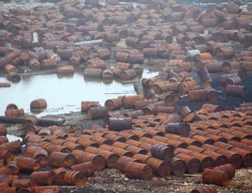
Magnetometers
Geometrics G858 magnetometer is a geophysical instrument that measures the strength of a magnetic field. Unexpected buried metal can be associated with UST’s, drum disposals, wells, manhole covers, storm drains, steel pipes, and other objects that may contribute to the development of sinkholes and voids. With the exception of cultural interference, nearby iron (type a magnet is attracted too) disrupts the earth’s magnetic field. The Geometrics G858 magnetometer is a device of unparalleled accuracy and sensitivity. It allows operators to identify slight alterations in the earth’s magnetic field. A magnetometer is an integral tool for anyone searching for magnetic metal. Magnetometers provide extraordinary precision when measuring and analyzing both 1-D and 2-D applications, reaching depths well over 30ft, which is far beyond the capability of classic metal detectors.
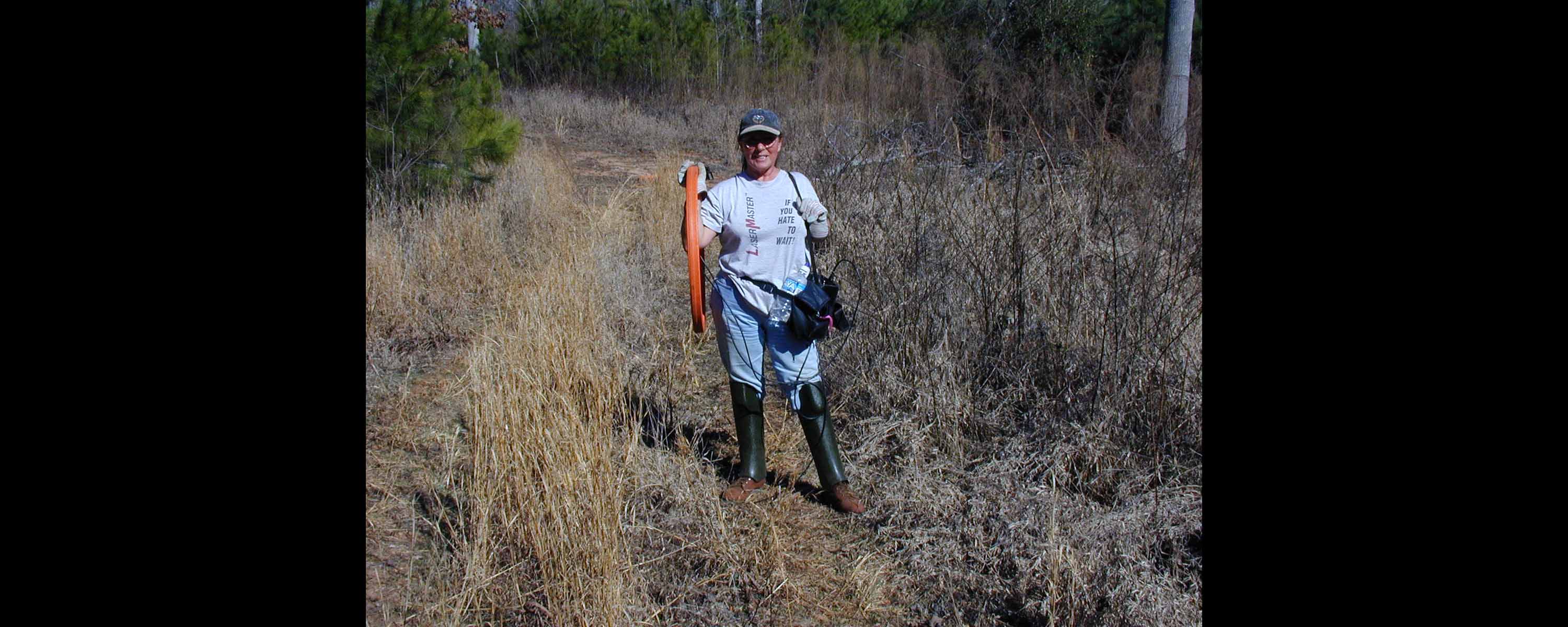
Cable, Pipe, and Line Locators
Traditional line locators are specialized tools with a specific purpose: to locate cables and pipelines that lie beneath the surface. Fortunately, these instruments are non-intrusive, making them an efficient way of locating underground facilities. Units are composed of two parts – a transmitter and a receiver. Working together, the receiver provides a way to track electromagnetic fields that radiate from a target produced by the transmitter. By carefully monitoring the response, an operator can identify buried metal objects such as pipes, cables, manhole covers, and storm drains that are hidden beneath the surface. As mentioned above, these features may be associated with unwanted drainage or groundwater flow that leads to voids or the unexpected movement of soils or construction fill. Furthermore, line locators do not require borings or an excavation.
Benefits of using geophysical methods for detecting voids and mapping potential causes
Geophysical methods are a powerful and cost-effective tool for void detection and mapping potential causes. Non-destructive testing has made it possible to survey large areas quickly and reliably, compared to traditional excavation and drilling methods. This helps to mitigate cost and risk associated with construction projects; something invaluable in today’s high stakes environments. As discussed above, the non-destructive testing offers a suite of geophysical surveys to characterize spatially extensive areas quickly and reliably. Near surface geophysical methods can detect and/or map possible areas of concern that are otherwise invisible to the naked eye and traditional testing methods. This offers invaluable insight into potentially dangerous problems such as sinkholes, compromised underground storage tanks (USTs), and drain tiles that, if left unchecked, could prove catastrophic.
The cost effectiveness and added safety provided by geophysical methods make them the go-to option for many types of construction or site evaluation projects in today’s business world. From helping contractors manage cost and risk associated with building, to giving site engineers invaluable information on the subsurface environment prior to excavation or drilling. Geophysics is a powerful tool when used correctly. Besides aiding in void detection and mapping potential causes, geophysical methods also provide an early warning system to identify potentially problematic conditions before they become a costly problem down the line.
Examples of successful applications with geophysical methods
Geophysical methods have been highly successful in a variety of different applications, proving to be an invaluable tool for optimization and safety. In particular, the use of geophysics has aided in the discovery of sinkholes, storm drains and tile lines, epikarst geology as well as providing confirmation of possible bedrock faults and fractures. Geophysical methods have also proven to be helpful for the detection and mapping of compromised septic tanks or underground storage tanks (USTs) in commercial properties.
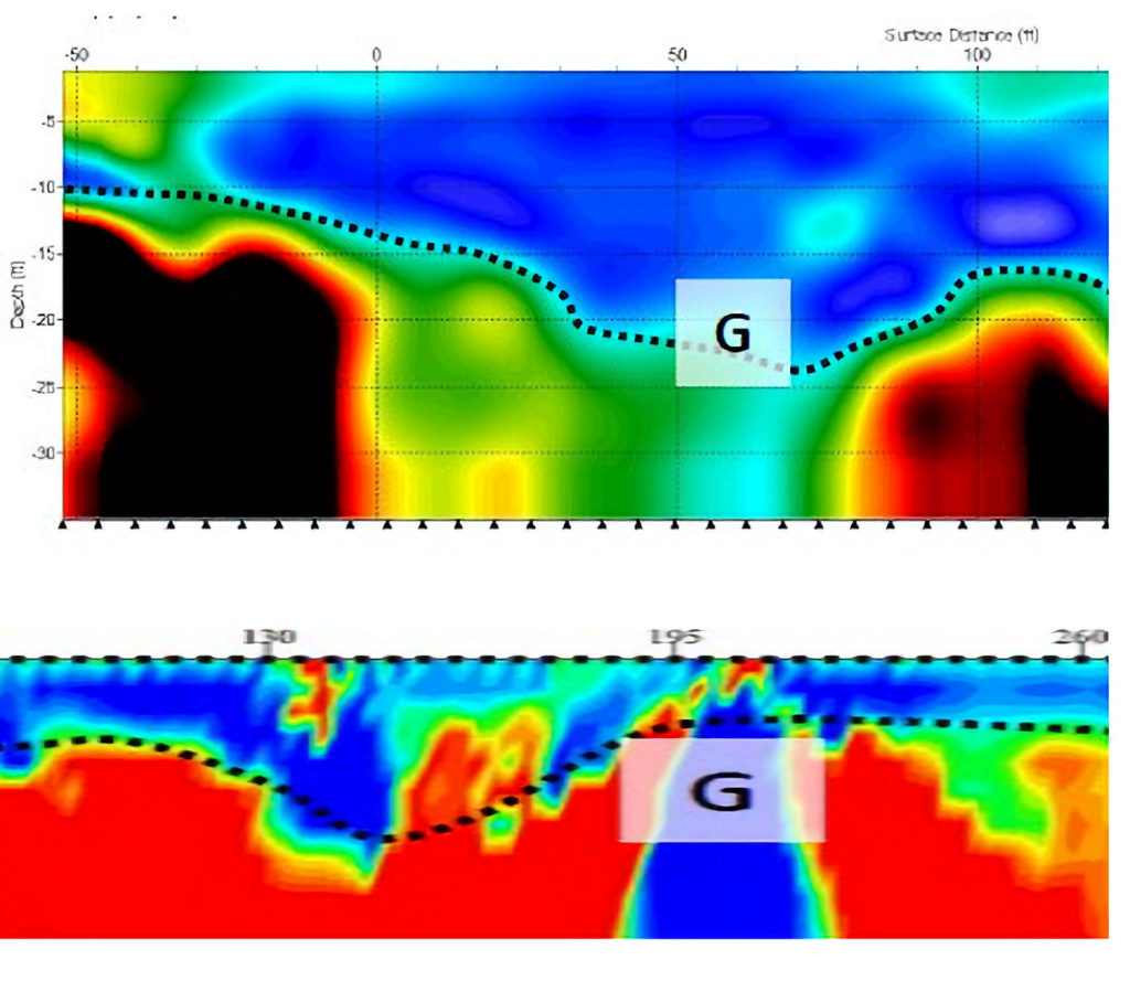
Geophysics, ERI, and MASW for Locating Voids and Sinkholes
The following is an account of how a combination of ERI and MASW geophysical surveys were used to identify major sinkholes (anomaly G) in a commercial parking lot known for its high volume of semi-trucks. The services were requested because unusual indications of differential settling made it essential to evaluate if subsidence within the storage area was an immediate concern. Given the heavy loads and big equipment, the uncontrolled appearance of a sinkhole could lead to hazardous circumstances. After sinkholes were confirmed using boring methods, remediation occurred at multiple locations on the property.
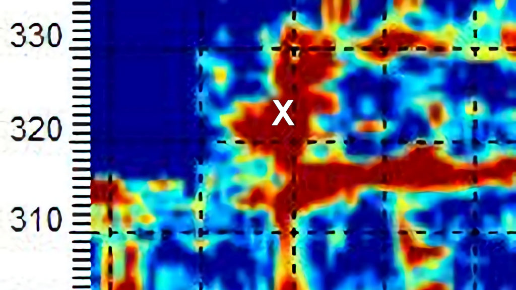
GPR for locating potential void spaces beneath a parking lot
A 200MHz Sensors & Software pulseEKKO Ultra GPR system was used to detect the potential for void spaces that could occur from soils washing away along preferential paths ways where water could flow. In this case, an unknown drain tile. Linear anomalies mapped out the drain tile, and a “X” marked area of interest displayed clear indications of a possible void or compromised soils. As heavy lift equipment routinely used this parking lot for loading and unloading cargo, further investigation in this 3 acre area was conducted.
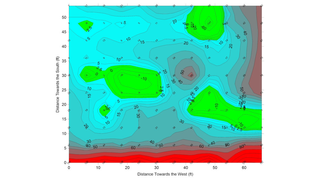
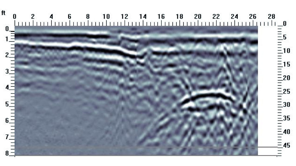
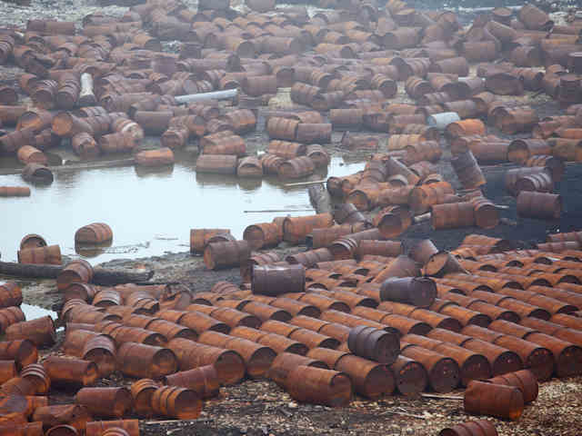
Geophysics for Locating Buried Tanks That May Produce Voids
EM31 and GPR methods were utilized to identify buried tanks at this case history. The Geonics EM31 was used to screen the site for large metal objects beneath the surface, resulting in the green-shaded areas interpreted as potential underground tanks. This was supported by a GPR transect that crossed perpendicular to the suspected long access of the tank. The GPR cross-section results confirmed the presence of a tank and also provided a delineation of the original excavation.
Challenges associated with using the geophysical methods
Utilizing geophysical methods often proves to be a difficult task, bringing with it its own unique set of struggles. First, it is important to note that clients should not envision geophysical techniques as a magical crystal ball that peers into the subsurface. Instead, one should see that scientific principles are fundamental to geophysical methods. Thus, surveys offer some of the best results when an operator has a budget to integrate two or more methods and collect closely spaced data. Furthermore, it is critical that there is good unrestricted access to the site and a reasonable amount of time to collect, process, analyze, and interpret the geophysical data. In other words, a under budgeted under sampled minimal effort can lead to results and interpretations that may not reflect site conditions or yield desirable results. It is prudent to perform sufficient levels of effort before any analysis or interpretations are drawn. Last of all, even if all efforts to utilize sound field methods are employed, it is still possible that geophysical surveys could fail to recognize small-scale features. This will be especially true if not enough time and preparation have been dedicated in advance to anticipate such conditions.
Summary of benefits and challenges when using GPR, MASW, EM, ERI, magnetometers, and line locators
A multi-discipline approach is often best when locating and mapping areas of concern around and under buildings, floors, parking lots, factories etc. Ground penetrating radar (GPR), multichannel analysis of surface waves (MASW), electrical resistance imaging (ERI), magnetometers, line locators and other techniques have been used in both academic research studies and industrial applications to narrow the search area and characterize spatially large areas effectively. Whether searching for voids, sinkholes, storm drains or compromised buried tanks, each of these techniques offers benefits in terms of cost-effectiveness, functionality, and accuracy. Sometimes, these technologies allow detailed subsurface imaging for relatively shallow depths (e.g. scanning concrete) whilst in others it permits high-resolution characterizations over large areas in a timely manner.
Despite these benefits there are associated drawbacks stemming from the physical limitations associated with each technique. Using geophysics for the location and mapping of voids, sink holes, compromised buried tanks, drain lines, storm drains, and potential areas of concern has its challenges. One of the biggest drawbacks are operators implementing too low level of an effort to get meaningful results (such as under sampling, not using all the tools available to them, and magical thinking). It is important to consider that a lack of expertise can yield results that do not correlate very well to actual conditions at the site. In some cases, this could ultimately undermine the intent of the geophysical services and contribute to the problem, potentially leading to more costly measures to mitigate risk or solve issues on site. If you are looking for more ideas pertaining to engineering, visit EngineeringGeophysics.com.

Leave A Comment